
Epson Printers
DIP Switch Settings on IDN Card |
DIP Switch Settings on Ethernet Card |
|
The 7 position DIP switch can be on the front panel of the IDN
Switch 1-4 determines the ID printer (1-15, default ID is 1). Switch 5-6 set the baud rate of the IDN interface (default 9600) Switch 7 is used to run the diagnostic test (default is off) |
If changing a printer to Ethernet you must change the specific dip switch on the Epson printer to allow for the Ethernet card. DIP SW2-8 On: refers to slide switch number 8, on switch bank 2, is turned On)
|
|
|
Configuration of Epson Series Printers to work with the IDN card
The Micros IDN module only supports 9600, 19200 and 38400 baud. The printer and the Micros IDN module must have the same baud rates to communicate. The printer must be configured like a serial interface. These settings change the printer to 9600 baud (8 bits, No parity, DTR/DSR handshaking) with a small receive buffer
Note: The Micros IDN module only supports 9600, 19200 and 38400 baud. The printer and the Micros IDN module must have the same baud rates to communicate. For TM-T88IV settings use the TM-88III settings.
Confirm the initial settings of the Printer
Run the printer self test (hold down the feed button while turning on the printer). The printer will print a list of initial settings including interface type and buffer capacity. Verify that the interface is "serial" for the Micros IDN adapter.
Self-Test - Running a Configuration Report
To Run the Config Report
For the EPSON TM-U200 printer:
Set DIP switch 1 on the Micros IDN Module to ON and power up the unit. After report has printed, power off unit and return DIP switch to the OFF position.
How to connect an Epson POS Printer with a Micros IDN Adapter
Cabling
Network Configuration
Installing Adapter
Setting IDN Address
Configuring Printer
Troubleshooting
A Micros IDN connection uses a Micros controller to connect to the POS printer. The printer plugs into the controller using RS422 patch cords.
Required Components
Cabling
Micros controllers supports up to 15 IDN devices along the same RS422 line. The IDN card must have a unique printer ID on the line. The card contains a series of switches that let you set the device ID from the default value of 1.
IDN cards use RS-422 patch cords
Tech Tip: Regular Serial (RS-232) versus RS-422
Though they are both serial protocols there is a difference between RS-232 and RS-422. RS-422 supports multi-drop, meaning more than 1 printer can exist on the physical line. RS-232 (9-pin serial) is single drop. RS232 cannot communicate with RS422 other without a converter. All RS422 cable runs should be 4000 feet or less, and all RS232 cable runs should be 50 feet or less. In environments with a high level of EMI, shorter runs may be required.
Note:
Some of the patch cords used by MICROS IDN devices use a 6-Pin RJ11 connector. Never plug this connector into an 8-pin RJ45 jack. The smaller body of the 6-pin connector can push pins 1 and 8 into the shielding around the jack, rendering the port inoperable.
Tech Tip: IDN Loopback Test
The IDN interface is a balanced RS-422 serial connection. A loopback test is a good way to test if the IDN is working. The test checks to see if the transmit and receive lines of the printer card are functioning by tying or looping the transmit line to the receive line on the card.
Making a loopback plug: Use an RJ25 (6P6C) male connector, or female jack with a cable. Wire pin 2 to pin 4, and pin 3 to pin 5; pin 1 is ground, and is not needed for this test. Note: pin 1 is the rightmost pin when RJ25 plug is held with plug end facing you, cable away from you, and locking clip facing down.
Simple DIY loopback plug
To use this plug in a test, use the following procedure:
(1) Turn OFF the TM-T88/TM-U220 printer
(2) On the IDN interface in back, turn ON dip switch #7 (IDN self test)
(3) Plug loopback test plug into either IDN port. Make sure printer has paper
(5) Turn ON printer. This will run the IDN self test.
(6) The resulting print-out will give the results of the IDN self test including the loopback test. Look for the "Loop Back With Test Plug" results towards the bottom of the list.
Loopback test results without plug (left) and with loopback plug in place (right)
Network Configuration
A hypothetical Micros installation, showing the drop to IDN devices
With RS-422 multi-drop printers can be 'threaded' along the same RS422 line through a series of incoming and outgoing patch cords. The last printer on the line does not require a return.
The Network Cluster Controller provides a means of using CAT 5 distribution with IDN (RS422 printer connection)
The right side of the patch panel shows an example of how to create a daisy chain or multi-drop line for IDN Printers. Each IDN printer (with the exception of the last printer in the line) requires a pair of patch cords to attach to the pair of Category 5 cable runs.
Steps for Installing Micros IDN Adapter
1. Disconnect power and other cables from the EPSON printer, and remove the printer DIP switch cover plate.
2. Remove the existing interface board from the printer by unscrewing 2 screws.
3. Properly align and push the new module into the printer. Fasten the two mounting screws through the faceplate of the new interface.
4. Set printer DIP switches as necessary; then attach the access cover.
5. Set the IDN DIP switches as necessary.
6. Connect the power cable to the printer and apply power.
7. Run a configuration report. This shows that the printer, module, and firmware are all installed and operating correctly and shows how the communication parameters are set.
The IDN adapter can replace the existing adapter and is held in place by 2 screws.
Note: If changing a printer to Micros IDN you must change the specific dip switch on the Epson printer to allow for the Micros IDN card.
Getting Initial Printer and IDN Adapter Settings
Get the initial settings of the Micros IDN adapter. Run the printer self test (hold down the feed button while turning on the printer). The printer will print a list of initial settings including interface type and buffer capacity. verify that the interface is "Micros IDN"
A similar test can them be done on the IDN adapter:
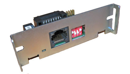
Faceplate of IDN adapter, DIP switch 7 is the leftmost switch in this view
DIP Switch Settings on IDN Card
The 7 position DIP switch can be on the front panel of the IDN
Switch 1-4 determines the ID printer (1-15, default ID is 1).
Switch 5-6 set the baud rate of the IDN interface (default is 9600 baud)
Switch 7 is used to run the diagnostic test (default is off)
Configuration of Epson Series Printers to work with the IDN card
The Micros IDN module only supports 9600, 19200 and 38400 baud. The printer and the Micros IDN module must have the same baud rates to communicate. The printer must be configured like a serial interface. These settings change the printer to 9600 baud (8 bits, No parity, DTR/DSR handshaking) with a small receive buffer
Note: The Micros IDN module only supports 9600, 19200 and 38400 baud. The printer and the Micros IDN module must have the same baud rates to communicate. For TM-T88IV settings use the TM-88III settings - see here.
Confirm the initial settings of the Printer
Run the printer self test (hold down the feed button while turning on the printer). The printer will print a list of initial settings including interface type and buffer capacity. Verify that the interface is "serial" for the Micros IDN adapter.
Location of DIP Switches on a TM-T88V and Switches to Set on Switch Bank 1 and Switch Bank 2
Self-Test - Running a Configuration Report
To Run the Config Report
For the EPSON TM-U200 printer:
Set DIP switch 1 on the Micros IDN Module to ON and power up the unit. After report has printed, power off unit and return DIP switch to the OFF position.
Installing the Device Drivers for Windows
Contact Micros for drivers for the IDN card.
There are no Windows drivers available for IDN card from Epson.
Connectivity Problems, never printed
No longer prints
A Micros IDN connection uses a Micros controller to connect to the POS printer. The printer plugs into the controller using RS422 patch cords.
Required Components
IDN cards use RS-422 patch cords
Tech Tip: Regular Serial (RS-232) versus RS-422
Though they are both serial protocols there is a difference between RS-232 and RS-422. RS-422 supports multi-drop, meaning more than 1 printer can exist on the physical line. RS-232 (9-pin serial) is single drop. RS232 cannot communicate with RS422 other without a converter. All RS422 cable runs should be 4000 feet or less, and all RS232 cable runs should be 50 feet or less. In environments with a high level of EMI, shorter runs may be required.
Note:
Some of the patch cords used by MICROS IDN devices use a 6-Pin RJ11 connector. Never plug this connector into an 8-pin RJ45 jack. The smaller body of the 6-pin connector can push pins 1 and 8 into the shielding around the jack, rendering the port inoperable.
Tech Tip: IDN Loopback Test
The IDN interface is a balanced RS-422 serial connection. A loopback test is a good way to test if the IDN is working. The test checks to see if the transmit and receive lines of the printer card are functioning by tying or looping the transmit line to the receive line on the card.
Making a loopback plug: Use an RJ25 (6P6C) male connector, or female jack with a cable. Wire pin 2 to pin 4, and pin 3 to pin 5; pin 1 is ground, and is not needed for this test. Note: pin 1 is the rightmost pin when RJ25 plug is held with plug end facing you, cable away from you, and locking clip facing down.
Simple DIY loopback plug
To use this plug in a test, use the following procedure:
(1) Turn OFF the TM-T88/TM-U220 printer
(2) On the IDN interface in back, turn ON dip switch #7 (IDN self test)
(3) Plug loopback test plug into either IDN port. Make sure printer has paper
(5) Turn ON printer. This will run the IDN self test.
(6) The resulting print-out will give the results of the IDN self test including the loopback test. Look for the "Loop Back With Test Plug" results towards the bottom of the list.
Loopback test results without plug (left) and with loopback plug in place (right)
Network Configuration
A hypothetical Micros installation, showing the drop to IDN devices
With RS-422 multi-drop printers can be 'threaded' along the same RS422 line through a series of incoming and outgoing patch cords. The last printer on the line does not require a return.
The Network Cluster Controller provides a means of using CAT 5 distribution with IDN (RS422 printer connection)
The right side of the patch panel shows an example of how to create a daisy chain or multi-drop line for IDN Printers. Each IDN printer (with the exception of the last printer in the line) requires a pair of patch cords to attach to the pair of Category 5 cable runs.
Steps for Installing Micros IDN Adapter
1. Disconnect power and other cables from the EPSON printer, and remove the printer DIP switch cover plate.
2. Remove the existing interface board from the printer by unscrewing 2 screws.
3. Properly align and push the new module into the printer. Fasten the two mounting screws through the faceplate of the new interface.
4. Set printer DIP switches as necessary; then attach the access cover.
5. Set the IDN DIP switches as necessary.
6. Connect the power cable to the printer and apply power.
7. Run a configuration report. This shows that the printer, module, and firmware are all installed and operating correctly and shows how the communication parameters are set.
The IDN adapter can replace the existing adapter and is held in place by 2 screws.
Note: If changing a printer to Micros IDN you must change the specific dip switch on the Epson printer to allow for the Micros IDN card.
Getting Initial Printer and IDN Adapter Settings
Get the initial settings of the Micros IDN adapter. Run the printer self test (hold down the feed button while turning on the printer). The printer will print a list of initial settings including interface type and buffer capacity. verify that the interface is "Micros IDN"
A similar test can them be done on the IDN adapter:
Faceplate of IDN adapter, DIP switch 7 is the leftmost switch in this view
Setting Address - DIP Switch Settings on IDN Card
The 7 position DIP switch can be on the front panel of the IDN
Switch 1-4 determines the ID printer (1-15, default ID is 1).
Switch 5-6 set the baud rate of the IDN interface (default is 9600 baud)
Switch 7 is used to run the diagnostic test (default is off)
Configuration of Epson Series Printers to work with the IDN card
The Micros IDN module only supports 9600, 19200 and 38400 baud. The printer and the Micros IDN module must have the same baud rates to communicate. The printer must be configured like a serial interface. These settings change the printer to 9600 baud (8 bits, No parity, DTR/DSR handshaking) with a small receive buffer
Note: The Micros IDN module only supports 9600, 19200 and 38400 baud. The printer and the Micros IDN module must have the same baud rates to communicate. For TM-T88IV settings use the TM-88III settings - see here.
Confirm the initial settings of the Printer
Run the printer self test (hold down the feed button while turning on the printer). The printer will print a list of initial settings including interface type and buffer capacity. Verify that the interface is "serial" for the Micros IDN adapter.
Location of DIP Switches on a TM-T88V and Switches to Set on Switch Bank 1 and Switch Bank 2
Self-Test - Running a Configuration Report
To Run the Config Report
For the EPSON TM-U200 printer:
Set DIP switch 1 on the Micros IDN Module to ON and power up the unit. After report has printed, power off unit and return DIP switch to the OFF position.
Installing the Device Drivers for Windows
Contact Micros for drivers for the IDN card.
There are no Windows drivers available for IDN card from Epson.
Troubleshooting
Connectivity Problems, never printed
No longer prints
A Micros IDN connection uses a Micros controller to connect to the POS printer. The printer plugs into the controller using RS422 patch cords.
Required Components
Cabling
Micros controllers supports up to 15 IDN devices along the same RS422 line. The IDN card must have a unique printer ID on the line. The card contains a series of switches that let you set the device ID from the default value of 1.
IDN cards use RS-422 patch cords
Tech Tip: Regular Serial (RS-232) versus RS-422
Though they are both serial protocols there is a difference between RS-232 and RS-422. RS-422 supports multi-drop, meaning more than 1 printer can exist on the physical line. RS-232 (9-pin serial) is single drop. RS232 cannot communicate with RS422 other without a converter. All RS422 cable runs should be 4000 feet or less, and all RS232 cable runs should be 50 feet or less. In environments with a high level of EMI, shorter runs may be required.
Note:
Some of the patch cords used by MICROS IDN devices use a 6-Pin RJ11 connector. Never plug this connector into an 8-pin RJ45 jack. The smaller body of the 6-pin connector can push pins 1 and 8 into the shielding around the jack, rendering the port inoperable.
Tech Tip: IDN Loopback Test
The IDN interface is a balanced RS-422 serial connection. A loopback test is a good way to test if the IDN is working. The test checks to see if the transmit and receive lines of the printer card are functioning by tying or looping the transmit line to the receive line on the card.
Making a loopback plug: Use an RJ25 (6P6C) male connector, or female jack with a cable. Wire pin 2 to pin 4, and pin 3 to pin 5; pin 1 is ground, and is not needed for this test. Note: pin 1 is the rightmost pin when RJ25 plug is held with plug end facing you, cable away from you, and locking clip facing down.
Simple DIY loopback plug
To use this plug in a test, use the following procedure:
(1) Turn OFF the TM-T88/TM-U220 printer
(2) On the IDN interface in back, turn ON dip switch #7 (IDN self test)
(3) Plug loopback test plug into either IDN port. Make sure printer has paper
(5) Turn ON printer. This will run the IDN self test.
(6) The resulting print-out will give the results of the IDN self test including the loopback test. Look for the "Loop Back With Test Plug" results towards the bottom of the list.
Loopback test results without plug (left) and with loopback plug in place (right)
Network Configuration
A hypothetical Micros installation, showing the drop to IDN devices
With RS-422 multi-drop printers can be 'threaded' along the same RS422 line through a series of incoming and outgoing patch cords. The last printer on the line does not require a return.
The Network Cluster Controller provides a means of using CAT 5 distribution with IDN (RS422 printer connection)
The right side of the patch panel shows an example of how to create a daisy chain or multi-drop line for IDN Printers. Each IDN printer (with the exception of the last printer in the line) requires a pair of patch cords to attach to the pair of Category 5 cable runs.
Installation Steps for Installing Micros IDN Adapter
1. Disconnect power and other cables from the EPSON printer, and remove the printer DIP switch cover plate.
2. Remove the existing interface board from the printer by unscrewing 2 screws.
3. Properly align and push the new module into the printer. Fasten the two mounting screws through the faceplate of the new interface.
4. Set printer DIP switches as necessary; then attach the access cover.
5. Set the IDN DIP switches as necessary.
6. Connect the power cable to the printer and apply power.
7. Run a configuration report. This shows that the printer, module, and firmware are all installed and operating correctly and shows how the communication parameters are set.
The IDN adapter can replace the existing adapter and is held in place by 2 screws.
Note: If changing a printer to Micros IDN you must change the specific dip switch on the Epson printer to allow for the Micros IDN card.
Getting Initial Printer and IDN Adapter Settings
Get the initial settings of the Micros IDN adapter. Run the printer self test (hold down the feed button while turning on the printer). The printer will print a list of initial settings including interface type and buffer capacity. verify that the interface is "Micros IDN"
A similar test can them be done on the IDN adapter:
Faceplate of IDN adapter, DIP switch 7 is the leftmost switch in this view
Setting Address - DIP Switch Settings on IDN Card
The 7 position DIP switch can be on the front panel of the IDN
Switch 1-4 determines the ID printer (1-15, default ID is 1).
Switch 5-6 set the baud rate of the IDN interface (default is 9600 baud)
Switch 7 is used to run the diagnostic test (default is off)
Configuration of Epson Series Printers to work with the IDN card
The Micros IDN module only supports 9600, 19200 and 38400 baud. The printer and the Micros IDN module must have the same baud rates to communicate. The printer must be configured like a serial interface. These settings change the printer to 9600 baud (8 bits, No parity, DTR/DSR handshaking) with a small receive buffer
Note: The Micros IDN module only supports 9600, 19200 and 38400 baud. The printer and the Micros IDN module must have the same baud rates to communicate. For TM-T88IV settings use the TM-88III settings - see here.
Confirm the initial settings of the Printer
Run the printer self test (hold down the feed button while turning on the printer). The printer will print a list of initial settings including interface type and buffer capacity. Verify that the interface is "serial" for the Micros IDN adapter.
Location of DIP Switches on a TM-T88V and Switches to Set on Switch Bank 1 and Switch Bank 2
Self-Test - Running a Configuration Report
To Run the Config Report
For the EPSON TM-U200 printer:
Set DIP switch 1 on the Micros IDN Module to ON and power up the unit. After report has printed, power off unit and return DIP switch to the OFF position.
Installing the Device Drivers for Windows
Contact Micros for drivers for the IDN card.
There are no Windows drivers available for IDN card from Epson.
Troubleshooting
Connectivity Problems, never printed
No longer prints
Confirm the initial settings of the Printer
Run the printer self test (hold down the feed button while turning on the printer). The printer will print a list of initial settings including interface type and buffer capacity. Verify that the interface is "serial" for the Micros IDN adapter.
Self-Test - Running a Configuration Report
To Run the Config Report
- Power on the printer,
- Open the paper cover,
- press the FEED button,
- Close the paper cover.
For the EPSON TM-U200 printer:
Set DIP switch 1 on the Micros IDN Module to ON and power up the unit. After report has printed, power off unit and return DIP switch to the OFF position.
How to connect an Epson POS Printer with a Micros IDN Adapter
Cabling
Network Configuration
Installing Adapter
Setting IDN Address
Configuring Printer
Troubleshooting
A Micros IDN connection uses a Micros controller to connect to the POS printer. The printer plugs into the controller using RS422 patch cords.
Required Components
- Epson POS Printer with Connect-It Micros IDN adapter
- Micros Cluster Controller or equivalent
(Local/Remote or Network Cluster Controller, including Micros 8700, 9700 or a NetCC Ethernet to RS422 converter)
- TM-T88II
- TM-T88III
- TM-T88IV
- TM-T88V
- TM-U220
- TM-U200
Cabling
Micros controllers supports up to 15 IDN devices along the same RS422 line. The IDN card must have a unique printer ID on the line. The card contains a series of switches that let you set the device ID from the default value of 1.
- Dual RJ-11 Female (adapter end)
IDN cards use RS-422 patch cords
Tech Tip: Regular Serial (RS-232) versus RS-422
Though they are both serial protocols there is a difference between RS-232 and RS-422. RS-422 supports multi-drop, meaning more than 1 printer can exist on the physical line. RS-232 (9-pin serial) is single drop. RS232 cannot communicate with RS422 other without a converter. All RS422 cable runs should be 4000 feet or less, and all RS232 cable runs should be 50 feet or less. In environments with a high level of EMI, shorter runs may be required.
Note:
Some of the patch cords used by MICROS IDN devices use a 6-Pin RJ11 connector. Never plug this connector into an 8-pin RJ45 jack. The smaller body of the 6-pin connector can push pins 1 and 8 into the shielding around the jack, rendering the port inoperable.
Tech Tip: IDN Loopback Test
The IDN interface is a balanced RS-422 serial connection. A loopback test is a good way to test if the IDN is working. The test checks to see if the transmit and receive lines of the printer card are functioning by tying or looping the transmit line to the receive line on the card.
Making a loopback plug: Use an RJ25 (6P6C) male connector, or female jack with a cable. Wire pin 2 to pin 4, and pin 3 to pin 5; pin 1 is ground, and is not needed for this test. Note: pin 1 is the rightmost pin when RJ25 plug is held with plug end facing you, cable away from you, and locking clip facing down.
Simple DIY loopback plug
To use this plug in a test, use the following procedure:
(1) Turn OFF the TM-T88/TM-U220 printer
(2) On the IDN interface in back, turn ON dip switch #7 (IDN self test)
(3) Plug loopback test plug into either IDN port. Make sure printer has paper
(5) Turn ON printer. This will run the IDN self test.
(6) The resulting print-out will give the results of the IDN self test including the loopback test. Look for the "Loop Back With Test Plug" results towards the bottom of the list.
Loopback test results without plug (left) and with loopback plug in place (right)
Network Configuration
A hypothetical Micros installation, showing the drop to IDN devices
With RS-422 multi-drop printers can be 'threaded' along the same RS422 line through a series of incoming and outgoing patch cords. The last printer on the line does not require a return.
The Network Cluster Controller provides a means of using CAT 5 distribution with IDN (RS422 printer connection)
The right side of the patch panel shows an example of how to create a daisy chain or multi-drop line for IDN Printers. Each IDN printer (with the exception of the last printer in the line) requires a pair of patch cords to attach to the pair of Category 5 cable runs.
Steps for Installing Micros IDN Adapter
1. Disconnect power and other cables from the EPSON printer, and remove the printer DIP switch cover plate.
2. Remove the existing interface board from the printer by unscrewing 2 screws.
3. Properly align and push the new module into the printer. Fasten the two mounting screws through the faceplate of the new interface.
4. Set printer DIP switches as necessary; then attach the access cover.
5. Set the IDN DIP switches as necessary.
6. Connect the power cable to the printer and apply power.
7. Run a configuration report. This shows that the printer, module, and firmware are all installed and operating correctly and shows how the communication parameters are set.
The IDN adapter can replace the existing adapter and is held in place by 2 screws.
Note: If changing a printer to Micros IDN you must change the specific dip switch on the Epson printer to allow for the Micros IDN card.
Getting Initial Printer and IDN Adapter Settings
Get the initial settings of the Micros IDN adapter. Run the printer self test (hold down the feed button while turning on the printer). The printer will print a list of initial settings including interface type and buffer capacity. verify that the interface is "Micros IDN"
A similar test can them be done on the IDN adapter:
Faceplate of IDN adapter, DIP switch 7 is the leftmost switch in this view
- Turn OFF printer
- Locate the series of 7 small switches on the faceplate of the IDN card
- Set module DIP switch #7 to ON
- Turn ON printer (don't press any buttons)
- After power on. the printer prints the diagnostic printout
- Power OFF the printer
- Reset DIP switch #7 to OFF
DIP Switch Settings on IDN Card
The 7 position DIP switch can be on the front panel of the IDN
Switch 1-4 determines the ID printer (1-15, default ID is 1).
Switch 5-6 set the baud rate of the IDN interface (default is 9600 baud)
Switch 7 is used to run the diagnostic test (default is off)
Configuration of Epson Series Printers to work with the IDN card
The Micros IDN module only supports 9600, 19200 and 38400 baud. The printer and the Micros IDN module must have the same baud rates to communicate. The printer must be configured like a serial interface. These settings change the printer to 9600 baud (8 bits, No parity, DTR/DSR handshaking) with a small receive buffer
Note: The Micros IDN module only supports 9600, 19200 and 38400 baud. The printer and the Micros IDN module must have the same baud rates to communicate. For TM-T88IV settings use the TM-88III settings - see here.
Confirm the initial settings of the Printer
Run the printer self test (hold down the feed button while turning on the printer). The printer will print a list of initial settings including interface type and buffer capacity. Verify that the interface is "serial" for the Micros IDN adapter.
Location of DIP Switches on a TM-T88V and Switches to Set on Switch Bank 1 and Switch Bank 2
Self-Test - Running a Configuration Report
To Run the Config Report
- Power on the printer,
- Open the paper cover,
- press the FEED button,
- Close the paper cover.
For the EPSON TM-U200 printer:
Set DIP switch 1 on the Micros IDN Module to ON and power up the unit. After report has printed, power off unit and return DIP switch to the OFF position.
Installing the Device Drivers for Windows
Contact Micros for drivers for the IDN card.
There are no Windows drivers available for IDN card from Epson.
Connectivity Problems, never printed
- The IDN address is wrong or is a duplicate. Check switch settings on the IDN card.
- The printer or the interface card is defective. Confirm printer operation with self-test. Confirm interface card by swapping with another interface card or printer.
- If printer prints random characters and beeps, it may be an indication that the DIP switches on the bottom of the printer are set incorrectly. The printer DIP switches are located on the bottom of the printer behind a small metal hatch that is held in place by a single Philips screw. for a TM-T88V, switches 1-2 1-7 and 2-7 should be on and the rest off. See the above picture for reference and colored the correct switch position in red. Up, away from the numbers, is on and down is off. Please make sure each switch is fully up or down, as being partially switched can also cause a problem.
- The interface settings are not the same on both the printer and computer. Run the printer self test to show the current settings on the printer. Check the computer side to see that interface is parallel. Settings can be changed on the printer using the DIP switches on the underside of the printer
- The printer selected in the software is not correct or the software doesn't support the printer in use.
No longer prints
- The TM printer is turned off. Turn on the TM printer. Confirm the connection of the power supply unit or the voltage of the commercial power.
- The TM printer is offline. Turn the TM printer online.
- The ERROR LED of the TM printer is on or flashing. Remove the error cause.
- The printing port of the driver on the computer side is not specified correctly. Confirm the driver setting on the computer side.
- The printer is not online in Windows. Check the status of the printer in the Windows Control Panel, the printer should show status as ready. Tip: try stopping and restarting the Print Spooler from the Services applet of the Control Panel.
- There are problems with the computer. Printing speed may go down due to problems with the network system or applications. Run the printer self test to confirm the printer is capable of printing at its normal speed
A Micros IDN connection uses a Micros controller to connect to the POS printer. The printer plugs into the controller using RS422 patch cords.
Required Components
- Epson POS Printer with Connect-It Micros IDN adapter
- Micros Cluster Controller or equivalent
(Local/Remote or Network Cluster Controller, including Micros 8700, 9700 or a NetCC Ethernet to RS422 converter).
- Dual RJ-11 Female (adapter end)
IDN cards use RS-422 patch cords
Tech Tip: Regular Serial (RS-232) versus RS-422
Though they are both serial protocols there is a difference between RS-232 and RS-422. RS-422 supports multi-drop, meaning more than 1 printer can exist on the physical line. RS-232 (9-pin serial) is single drop. RS232 cannot communicate with RS422 other without a converter. All RS422 cable runs should be 4000 feet or less, and all RS232 cable runs should be 50 feet or less. In environments with a high level of EMI, shorter runs may be required.
Note:
Some of the patch cords used by MICROS IDN devices use a 6-Pin RJ11 connector. Never plug this connector into an 8-pin RJ45 jack. The smaller body of the 6-pin connector can push pins 1 and 8 into the shielding around the jack, rendering the port inoperable.
Tech Tip: IDN Loopback Test
The IDN interface is a balanced RS-422 serial connection. A loopback test is a good way to test if the IDN is working. The test checks to see if the transmit and receive lines of the printer card are functioning by tying or looping the transmit line to the receive line on the card.
Making a loopback plug: Use an RJ25 (6P6C) male connector, or female jack with a cable. Wire pin 2 to pin 4, and pin 3 to pin 5; pin 1 is ground, and is not needed for this test. Note: pin 1 is the rightmost pin when RJ25 plug is held with plug end facing you, cable away from you, and locking clip facing down.
Simple DIY loopback plug
To use this plug in a test, use the following procedure:
(1) Turn OFF the TM-T88/TM-U220 printer
(2) On the IDN interface in back, turn ON dip switch #7 (IDN self test)
(3) Plug loopback test plug into either IDN port. Make sure printer has paper
(5) Turn ON printer. This will run the IDN self test.
(6) The resulting print-out will give the results of the IDN self test including the loopback test. Look for the "Loop Back With Test Plug" results towards the bottom of the list.
Loopback test results without plug (left) and with loopback plug in place (right)
Network Configuration
A hypothetical Micros installation, showing the drop to IDN devices
With RS-422 multi-drop printers can be 'threaded' along the same RS422 line through a series of incoming and outgoing patch cords. The last printer on the line does not require a return.
The Network Cluster Controller provides a means of using CAT 5 distribution with IDN (RS422 printer connection)
The right side of the patch panel shows an example of how to create a daisy chain or multi-drop line for IDN Printers. Each IDN printer (with the exception of the last printer in the line) requires a pair of patch cords to attach to the pair of Category 5 cable runs.
Steps for Installing Micros IDN Adapter
1. Disconnect power and other cables from the EPSON printer, and remove the printer DIP switch cover plate.
2. Remove the existing interface board from the printer by unscrewing 2 screws.
3. Properly align and push the new module into the printer. Fasten the two mounting screws through the faceplate of the new interface.
4. Set printer DIP switches as necessary; then attach the access cover.
5. Set the IDN DIP switches as necessary.
6. Connect the power cable to the printer and apply power.
7. Run a configuration report. This shows that the printer, module, and firmware are all installed and operating correctly and shows how the communication parameters are set.
The IDN adapter can replace the existing adapter and is held in place by 2 screws.
Note: If changing a printer to Micros IDN you must change the specific dip switch on the Epson printer to allow for the Micros IDN card.
Getting Initial Printer and IDN Adapter Settings
Get the initial settings of the Micros IDN adapter. Run the printer self test (hold down the feed button while turning on the printer). The printer will print a list of initial settings including interface type and buffer capacity. verify that the interface is "Micros IDN"
A similar test can them be done on the IDN adapter:
Faceplate of IDN adapter, DIP switch 7 is the leftmost switch in this view
- Turn OFF printer
- Locate the series of 7 small switches on the faceplate of the IDN card
- Set module DIP switch #7 to ON
- Turn ON printer (don't press any buttons)
- After power on. the printer prints the diagnostic printout
- Power OFF the printer
- Reset DIP switch #7 to OFF
Setting Address - DIP Switch Settings on IDN Card
The 7 position DIP switch can be on the front panel of the IDN
Switch 1-4 determines the ID printer (1-15, default ID is 1).
Switch 5-6 set the baud rate of the IDN interface (default is 9600 baud)
Switch 7 is used to run the diagnostic test (default is off)
Configuration of Epson Series Printers to work with the IDN card
The Micros IDN module only supports 9600, 19200 and 38400 baud. The printer and the Micros IDN module must have the same baud rates to communicate. The printer must be configured like a serial interface. These settings change the printer to 9600 baud (8 bits, No parity, DTR/DSR handshaking) with a small receive buffer
Note: The Micros IDN module only supports 9600, 19200 and 38400 baud. The printer and the Micros IDN module must have the same baud rates to communicate. For TM-T88IV settings use the TM-88III settings - see here.
Confirm the initial settings of the Printer
Run the printer self test (hold down the feed button while turning on the printer). The printer will print a list of initial settings including interface type and buffer capacity. Verify that the interface is "serial" for the Micros IDN adapter.
Location of DIP Switches on a TM-T88V and Switches to Set on Switch Bank 1 and Switch Bank 2
Self-Test - Running a Configuration Report
To Run the Config Report
- Power on the printer,
- Open the paper cover,
- press the FEED button,
- Close the paper cover.
For the EPSON TM-U200 printer:
Set DIP switch 1 on the Micros IDN Module to ON and power up the unit. After report has printed, power off unit and return DIP switch to the OFF position.
Installing the Device Drivers for Windows
Contact Micros for drivers for the IDN card.
There are no Windows drivers available for IDN card from Epson.
Troubleshooting
Connectivity Problems, never printed
- The IDN address is wrong or is a duplicate. Check switch settings on the IDN card.
- The printer or the interface card is defective. Confirm printer operation with self-test. Confirm interface card by swapping with another interface card or printer.
- If printer prints random characters and beeps, it may be an indication that the DIP switches on the bottom of the printer are set incorrectly. The printer DIP switches are located on the bottom of the printer behind a small metal hatch that is held in place by a single Philips screw. for a TM-T88V, switches 1-2 1-7 and 2-7 should be on and the rest off. See the above picture for reference and colored the correct switch position in red. Up, away from the numbers, is on and down is off. Please make sure each switch is fully up or down, as being partially switched can also cause a problem.
- The interface settings are not the same on both the printer and computer. Run the printer self test to show the current settings on the printer. Check the computer side to see that interface is parallel. Settings can be changed on the printer using the DIP switches on the underside of the printer
- The printer selected in the software is not correct or the software doesn't support the printer in use.
No longer prints
- The TM printer is turned off. Turn on the TM printer. Confirm the connection of the power supply unit or the voltage of the commercial power.
- The TM printer is offline. Turn the TM printer online.
- The ERROR LED of the TM printer is on or flashing. Remove the error cause.
- The printing port of the driver on the computer side is not specified correctly. Confirm the driver setting on the computer side.
- The printer is not online in Windows. Check the status of the printer in the Windows Control Panel, the printer should show status as ready. Tip: try stopping and restarting the Print Spooler from the Services applet of the Control Panel.
- There are problems with the computer. Printing speed may go down due to problems with the network system or applications. Run the printer self test to confirm the printer is capable of printing at its normal speed
A Micros IDN connection uses a Micros controller to connect to the POS printer. The printer plugs into the controller using RS422 patch cords.
Required Components
- Epson POS Printer with Connect-It Micros IDN adapter
- Micros Cluster Controller or equivalent
(Local/Remote or Network Cluster Controller, including Micros 8700, 9700 or a NetCC Ethernet to RS422 converter).
- TM-T88II
- TM-T88III
- TM-T88IV
- TM-T88V
- TM-U220
- TM-U200
Cabling
Micros controllers supports up to 15 IDN devices along the same RS422 line. The IDN card must have a unique printer ID on the line. The card contains a series of switches that let you set the device ID from the default value of 1.
- Dual RJ-11 Female (adapter end)
IDN cards use RS-422 patch cords
Tech Tip: Regular Serial (RS-232) versus RS-422
Though they are both serial protocols there is a difference between RS-232 and RS-422. RS-422 supports multi-drop, meaning more than 1 printer can exist on the physical line. RS-232 (9-pin serial) is single drop. RS232 cannot communicate with RS422 other without a converter. All RS422 cable runs should be 4000 feet or less, and all RS232 cable runs should be 50 feet or less. In environments with a high level of EMI, shorter runs may be required.
Note:
Some of the patch cords used by MICROS IDN devices use a 6-Pin RJ11 connector. Never plug this connector into an 8-pin RJ45 jack. The smaller body of the 6-pin connector can push pins 1 and 8 into the shielding around the jack, rendering the port inoperable.
Tech Tip: IDN Loopback Test
The IDN interface is a balanced RS-422 serial connection. A loopback test is a good way to test if the IDN is working. The test checks to see if the transmit and receive lines of the printer card are functioning by tying or looping the transmit line to the receive line on the card.
Making a loopback plug: Use an RJ25 (6P6C) male connector, or female jack with a cable. Wire pin 2 to pin 4, and pin 3 to pin 5; pin 1 is ground, and is not needed for this test. Note: pin 1 is the rightmost pin when RJ25 plug is held with plug end facing you, cable away from you, and locking clip facing down.
Simple DIY loopback plug
To use this plug in a test, use the following procedure:
(1) Turn OFF the TM-T88/TM-U220 printer
(2) On the IDN interface in back, turn ON dip switch #7 (IDN self test)
(3) Plug loopback test plug into either IDN port. Make sure printer has paper
(5) Turn ON printer. This will run the IDN self test.
(6) The resulting print-out will give the results of the IDN self test including the loopback test. Look for the "Loop Back With Test Plug" results towards the bottom of the list.
Loopback test results without plug (left) and with loopback plug in place (right)
Network Configuration
A hypothetical Micros installation, showing the drop to IDN devices
With RS-422 multi-drop printers can be 'threaded' along the same RS422 line through a series of incoming and outgoing patch cords. The last printer on the line does not require a return.
The Network Cluster Controller provides a means of using CAT 5 distribution with IDN (RS422 printer connection)
The right side of the patch panel shows an example of how to create a daisy chain or multi-drop line for IDN Printers. Each IDN printer (with the exception of the last printer in the line) requires a pair of patch cords to attach to the pair of Category 5 cable runs.
Installation Steps for Installing Micros IDN Adapter
1. Disconnect power and other cables from the EPSON printer, and remove the printer DIP switch cover plate.
2. Remove the existing interface board from the printer by unscrewing 2 screws.
3. Properly align and push the new module into the printer. Fasten the two mounting screws through the faceplate of the new interface.
4. Set printer DIP switches as necessary; then attach the access cover.
5. Set the IDN DIP switches as necessary.
6. Connect the power cable to the printer and apply power.
7. Run a configuration report. This shows that the printer, module, and firmware are all installed and operating correctly and shows how the communication parameters are set.
The IDN adapter can replace the existing adapter and is held in place by 2 screws.
Note: If changing a printer to Micros IDN you must change the specific dip switch on the Epson printer to allow for the Micros IDN card.
Getting Initial Printer and IDN Adapter Settings
Get the initial settings of the Micros IDN adapter. Run the printer self test (hold down the feed button while turning on the printer). The printer will print a list of initial settings including interface type and buffer capacity. verify that the interface is "Micros IDN"
A similar test can them be done on the IDN adapter:
Faceplate of IDN adapter, DIP switch 7 is the leftmost switch in this view
- Turn OFF printer
- Locate the series of 7 small switches on the faceplate of the IDN card
- Set module DIP switch #7 to ON
- Turn ON printer (don't press any buttons)
- After power on. the printer prints the diagnostic printout
- Power OFF the printer
- Reset DIP switch #7 to OFF
Setting Address - DIP Switch Settings on IDN Card
The 7 position DIP switch can be on the front panel of the IDN
Switch 1-4 determines the ID printer (1-15, default ID is 1).
Switch 5-6 set the baud rate of the IDN interface (default is 9600 baud)
Switch 7 is used to run the diagnostic test (default is off)
Configuration of Epson Series Printers to work with the IDN card
The Micros IDN module only supports 9600, 19200 and 38400 baud. The printer and the Micros IDN module must have the same baud rates to communicate. The printer must be configured like a serial interface. These settings change the printer to 9600 baud (8 bits, No parity, DTR/DSR handshaking) with a small receive buffer
Note: The Micros IDN module only supports 9600, 19200 and 38400 baud. The printer and the Micros IDN module must have the same baud rates to communicate. For TM-T88IV settings use the TM-88III settings - see here.
Confirm the initial settings of the Printer
Run the printer self test (hold down the feed button while turning on the printer). The printer will print a list of initial settings including interface type and buffer capacity. Verify that the interface is "serial" for the Micros IDN adapter.
Location of DIP Switches on a TM-T88V and Switches to Set on Switch Bank 1 and Switch Bank 2
Self-Test - Running a Configuration Report
To Run the Config Report
- Power on the printer,
- Open the paper cover,
- press the FEED button,
- Close the paper cover.
For the EPSON TM-U200 printer:
Set DIP switch 1 on the Micros IDN Module to ON and power up the unit. After report has printed, power off unit and return DIP switch to the OFF position.
Installing the Device Drivers for Windows
Contact Micros for drivers for the IDN card.
There are no Windows drivers available for IDN card from Epson.
Troubleshooting
Connectivity Problems, never printed
- The IDN address is wrong or is a duplicate. Check switch settings on the IDN card.
- The printer or the interface card is defective. Confirm printer operation with self-test. Confirm interface card by swapping with another interface card or printer.
- If printer prints random characters and beeps, it may be an indication that the DIP switches on the bottom of the printer are set incorrectly. The printer DIP switches are located on the bottom of the printer behind a small metal hatch that is held in place by a single Philips screw. for a TM-T88V, switches 1-2 1-7 and 2-7 should be on and the rest off. See the above picture for reference and colored the correct switch position in red. Up, away from the numbers, is on and down is off. Please make sure each switch is fully up or down, as being partially switched can also cause a problem.
- The interface settings are not the same on both the printer and computer. Run the printer self test to show the current settings on the printer. Check the computer side to see that interface is parallel. Settings can be changed on the printer using the DIP switches on the underside of the printer
- The printer selected in the software is not correct or the software doesn't support the printer in use.
No longer prints
- The TM printer is turned off. Turn on the TM printer. Confirm the connection of the power supply unit or the voltage of the commercial power.
- The TM printer is offline. Turn the TM printer online.
- The ERROR LED of the TM printer is on or flashing. Remove the error cause.
- The printing port of the driver on the computer side is not specified correctly. Confirm the driver setting on the computer side.
- The printer is not online in Windows. Check the status of the printer in the Windows Control Panel, the printer should show status as ready. Tip: try stopping and restarting the Print Spooler from the Services applet of the Control Panel.
- There are problems with the computer. Printing speed may go down due to problems with the network system or applications. Run the printer self test to confirm the printer is capable of printing at its normal speed
How to connect an Epson POS Printer with an Ethernet Adapter
The installation step vary slighting depending on the type of Ethernet card you have.
Over the past few years Epson has offered 3 types of Ethernet cards, Type II, II and IV. Each has a different set of features and a different way of setting them up.
Over the past few years Epson has offered 3 types of Ethernet cards, Type II, II and IV. Each has a different set of features and a different way of setting them up.
Type II
Type III
Type IV
Installation - Type IV
Installation Steps for Installing Ethernet Adapter (Type IV)
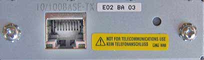
The Type IV module (UB-E02 or similar) is the latest type of Connect-It Ethernet adapter. The module can be set by accessing it directly using a web browser or by a configuration utility. This type of module can also act as a device type Print server to be used by more than 1 computer.
Installing and Setting the Connect-It Ethernet Adapter (Type IV)
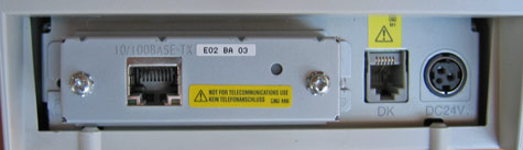
Install the Connect-It Ethernet adapter into the Epson TM series printer
Installation Steps for Installing Ethernet Adapter (Type IV)
The Type IV module (UB-E02 or similar) is the latest type of Connect-It Ethernet adapter. The module can be set by accessing it directly using a web browser or by a configuration utility. This type of module can also act as a device type Print server to be used by more than 1 computer.
Installing and Setting the Connect-It Ethernet Adapter (Type IV)
Install the Connect-It Ethernet adapter into the Epson TM series printer
The Type IV adapter can replace the existing adapter and is held in place by 2 screws
Getting initial printer and Ethernet adapter settings (Type IV)
Get the initial settings of the Ethernet adapter. Run the printer self test (hold down the feed button while turning on the printer). The printer will print a list of initial settings including interface type and buffer capacity. verify that the interface is "Ethernet"
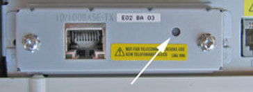
A similar test can then be done on the UB-EO2 adapter by inserting a paperclip through the small hole in the adapter for 3 seconds
Get the initial settings of the Ethernet adapter. Run the printer self test (hold down the feed button while turning on the printer). The printer will print a list of initial settings including interface type and buffer capacity. verify that the interface is "Ethernet"
A similar test can then be done on the UB-EO2 adapter by inserting a paperclip through the small hole in the adapter for 3 seconds
Changing the IP Address of the Adapter
Now comes the tricky part. To be able to change the IP address on the adapter you need to be able to connect with it. To do this you most likely need to change the IP address of your computer to a value that makes the adapter accessible. You can then connect to the adapter, make the change to the adapter, then return the computer back to it's original settings.
Resetting the Adapter
You can reset the UB-E02 Ethernet Interface card to factory defaults by holding down the push button on the card (see arrow above) while turning on the printer power and continuing to hold it down for 5 seconds. This causes all internal settings to return to their factory defaults.
Setting the IP Address on your Computer
In Windows you can access the wired Ethernet adapter in the "Network Connections" applet in the Windows Control Panels (Internet Protocol/TCP/IP properties, allow you to enter an IP address.) Make a note of the existing settings, you'll be returning to those settings when your done. Set the IP address to an address in the same domain as the adapter. For example of the adapter shows an IP address of 172.16.10.63 you could change the computer to 172.16.10.2. Do not set the computer to the same address as the Ethernet adapter on the printer. You might have to reset the computer's adapter for the new settings to take place.
Logging onto the Adapter using TMNet WebConfig (Type II or Type IV)
TMNet web configuration allows you to access the adapter via your network using a web browser. Generally speaking the adapter must be in the same sub domain as the computer to be able to log on (see previous section for how to configure the PC to the same subdomain)
Using a web browser such as Internet Explorer you should now be able to connect to the adapter by entering the IP address of the adapter directly into the address bar of the browser. The TMNet General Information page show open.
To change the IP address, select 'TCP/IP' under 'Configuration.' You can enter a new IP address and gateway address.
Press the 'Submit' button when done. The 'Submit' button with write settings to the printer. The Ethernet adapter is reset when you press the 'Reset' button.
Setting the IP Address using TMNet WinConfig (Type IV)
To use the UB-E02 with TCP/IP, you first need to set its IP address. You can set the IP address by using the EPSON TMNet WinConfig or arp/ping command.
Running the TMNet WinNet configuration utility on the Computer
Once connected you can run the TMNet configuration utility to view or change the settings on the Ethernet card.
To obtain the TMNet configuration utility from Epson:
1. Set the TCP/IP of your operating system.
2. Install the EPSON TMNet WinConfig.
3. Set the IP address using EPSON TMNet WinConfig.
The utility will scan for and should list the Ethernet printer
Select the printer and press Configuration to view or change settings. (Pressing the Launch Browser button will contact the TMNet WebConfig interface using your web browser.)
When you make changes and press 'OK' the utility sends the new settings to the printer and resets the printer. Note: the default password is <blank>. Don't forget to make the same changes on the computer side to maintain connectivity.
Setting the IP Address using TMNet WinConfig (Type IV)
To use the UB-E02 with TCP/IP, you first need to set its IP address. You can set the IP address by using the EPSON TMNet WinConfig or arp/ping command.
Running the TMNet WinNet configuration utility on the Computer
Once connected you can run the TMNet configuration utility to view or change the settings on the Ethernet card.
To obtain the TMNet configuration utility from Epson:
- You may have to re-enable your wired LAN port to download the EpsonTMNetWinConfig utility.
- Download and Install Epson’s TMNetWinConfig available from www.pos.epson.com
- Click on TECHNICAL RESOURCES
- Select Ethernet INTERFACES under the CONNECT-IT INTERFACES
- Click the download icon for the TMNetWinConfig
1. Set the TCP/IP of your operating system.
2. Install the EPSON TMNet WinConfig.
3. Set the IP address using EPSON TMNet WinConfig.
The utility will scan for and should list the Ethernet printer
Select the printer and press Configuration to view or change settings. (Pressing the Launch Browser button will contact the TMNet WebConfig interface using your web browser.)
When you make changes and press 'OK' the utility sends the new settings to the printer and resets the printer. Note: the default password is <blank>. Don't forget to make the same changes on the computer side to maintain connectivity.
TMNet WebConfig Interface
Ethernet Interface Settings
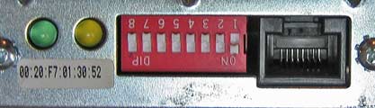
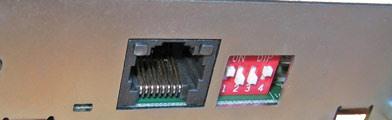
DIP Normal Switch Settings for the Ethernet III Module (front panel)
DS-1 Off ('On' is used to generate a configuration report)
DS-2 N/A
DS-3 N/A
DS-4 Allows external input
DS-1 Off ('On' is used to generate a configuration report)
DS-2 N/A
DS-3 N/A
DS-4 Allows external input
An Epson Type III Ethernet Interface Adapter
Jumper Settings (in strip together on circuit board)
JP-1 baud
JP-2 baud
JP-3 DHCP (default: on)
JP-4 factory use (normally off)
Baud rate settings (set using combination of jumper 1 and jumper 2, above)
9600 baud: JP1-Off, JP-2-Off
19200 baud: JP1-On, JP-2-Off
38400 baud: JP1-Off, JP-2-On
Note: The Ethernet III module only supports 9600, 19200 and 38400 baud rates.
The printer and the Ethernet III module must have the same baud rates to communicate.
Get the initial settings of the Printer
Run the printer self test (hold down the feed button while turning on the printer). The printer will print a list of initial settings including interface type and buffer capacity. Verify that the interface is "serial" for this type of Ethernet adapter and that the baud rate is the same as is set on the card. If necessary, change the baud rate on the printer (using the DIP switches) or the baud rate on the module (using jumpers), so they agree.
Get the initial settings of the Ethernet Adapter Card
Turn off power on printer. Change the dip switch 1 to ON. Turn printer on. The printer will print a list of including MAC address, current IP address and DIP switch and jumper settings.
Note: if you want to enable DHCP for this card, you must place a jumper on JP3. JP3 is located on the circuit board near the large black connector. DHCP stands for Dynamic Host Configuration Protocol, a network service that automatically assigns IP addresses to devices.
Installation Steps (Type II or Type III)
1. Disconnect power and other cables from the EPSON printer, and remove the printer DIP switch cover plate.
2. Remove the existing interface board from the printer by unscrewing 2 screws.
3. Properly align and push the new module into the printer. Fasten the two mounting screws through the faceplate of the new interface.
4. Set DIP switches as necessary; then attach the access cover.
5. Connect the power cable to the printer and apply power. Attach network cable.
6. Run a configuration report. This shows that the printer, module, and firmware are all installed and operating correctly and shows how the communication parameters are set.
Running a Configuration Report (Type II or Type III)
To Run the Config Report
For the EPSON TM-U200 printer:
Set DIP switch 1 on the Ethernet Module to ON and power up the unit. After report has printed, power off unit and return DIP switch to the OFF position.
Configuring the Interface (Type II or Type III)
Each Epson Ethernet Interface module has a 'Base' MAC Address programmed into the it. A unique MAC Address and a Serial Number are programmed into the Flash ROM at the factory, and cannot be changed. Labels with both the MAC address and serial number are affixed to the module. These numbers are important when configuring the adapter- It is advisable to make a note of these values in a secure place.
The Internet or IP address can be set using the web interface or Epson EEI utility. It can be dynamically reassigned via DHCP, BOOTP, or ARP/Ping.
High Level Configuration
Option 1 (Ethernet II only): Using a web browser, type the default IP address (found on a label on the interface card) into the address field of your web browser. The configuration screen should appear. The default password for the interface is Epson. We highly recommend this be changed. Once the web interface is running, all application, network, printer and password settings can be modified.
Option 2 (Ethernet II or Ethernet III): Use the Epson Ethernet Interface Configuration Program for this series of adapter, EEIUtil.exe, The program will discover all Epson Ethernet printers on your network and allow you to reconfigure them. Note: the TMNetWinConfig is not compatible with this model of adapter.
Important: If you are assigning a permanent IP address to the Epson printer, it is advised that dip switch 8 on the interface module by switched to off once the address has been set.
JP-1 baud
JP-2 baud
JP-3 DHCP (default: on)
JP-4 factory use (normally off)
Baud rate settings (set using combination of jumper 1 and jumper 2, above)
9600 baud: JP1-Off, JP-2-Off
19200 baud: JP1-On, JP-2-Off
38400 baud: JP1-Off, JP-2-On
Note: The Ethernet III module only supports 9600, 19200 and 38400 baud rates.
The printer and the Ethernet III module must have the same baud rates to communicate.
Get the initial settings of the Printer
Run the printer self test (hold down the feed button while turning on the printer). The printer will print a list of initial settings including interface type and buffer capacity. Verify that the interface is "serial" for this type of Ethernet adapter and that the baud rate is the same as is set on the card. If necessary, change the baud rate on the printer (using the DIP switches) or the baud rate on the module (using jumpers), so they agree.
Get the initial settings of the Ethernet Adapter Card
Turn off power on printer. Change the dip switch 1 to ON. Turn printer on. The printer will print a list of including MAC address, current IP address and DIP switch and jumper settings.
Note: if you want to enable DHCP for this card, you must place a jumper on JP3. JP3 is located on the circuit board near the large black connector. DHCP stands for Dynamic Host Configuration Protocol, a network service that automatically assigns IP addresses to devices.
Installation Steps (Type II or Type III)
1. Disconnect power and other cables from the EPSON printer, and remove the printer DIP switch cover plate.
2. Remove the existing interface board from the printer by unscrewing 2 screws.
3. Properly align and push the new module into the printer. Fasten the two mounting screws through the faceplate of the new interface.
4. Set DIP switches as necessary; then attach the access cover.
5. Connect the power cable to the printer and apply power. Attach network cable.
6. Run a configuration report. This shows that the printer, module, and firmware are all installed and operating correctly and shows how the communication parameters are set.
Running a Configuration Report (Type II or Type III)
To Run the Config Report
- Power on the printer,
- Open the paper cover,
- press the FEED button,
- Close the paper cover.
For the EPSON TM-U200 printer:
Set DIP switch 1 on the Ethernet Module to ON and power up the unit. After report has printed, power off unit and return DIP switch to the OFF position.
Configuring the Interface (Type II or Type III)
Each Epson Ethernet Interface module has a 'Base' MAC Address programmed into the it. A unique MAC Address and a Serial Number are programmed into the Flash ROM at the factory, and cannot be changed. Labels with both the MAC address and serial number are affixed to the module. These numbers are important when configuring the adapter- It is advisable to make a note of these values in a secure place.
The Internet or IP address can be set using the web interface or Epson EEI utility. It can be dynamically reassigned via DHCP, BOOTP, or ARP/Ping.
High Level Configuration
Option 1 (Ethernet II only): Using a web browser, type the default IP address (found on a label on the interface card) into the address field of your web browser. The configuration screen should appear. The default password for the interface is Epson. We highly recommend this be changed. Once the web interface is running, all application, network, printer and password settings can be modified.
Option 2 (Ethernet II or Ethernet III): Use the Epson Ethernet Interface Configuration Program for this series of adapter, EEIUtil.exe, The program will discover all Epson Ethernet printers on your network and allow you to reconfigure them. Note: the TMNetWinConfig is not compatible with this model of adapter.
Important: If you are assigning a permanent IP address to the Epson printer, it is advised that dip switch 8 on the interface module by switched to off once the address has been set.
How to connect an Epson TM Series Printer with a USB Adapter
Installing nd Setting the Connect-It USB Adapter
Install the Connect-It USB adapter into the Epson TM series printer
Install the Connect-It USB adapter into the Epson TM series printer
The adapter can replace the existing adapter and is held in place by 2 screws
Attaching the Cable
Use a standard USB 2.0 printer cable to connect the printer. One end has a male USB type B connector, the other end has a male USB type A plug that goes into the computer.
Use a standard USB 2.0 printer cable to connect the printer. One end has a male USB type B connector, the other end has a male USB type A plug that goes into the computer.


Getting Initial Printer and Connect-it Adapter Settings using Self Test
Get the initial settings of the USB adapter. Run the printer self test (hold down the feed button while turning on the printer). The printer will print a list of initial settings including interface type, ID, and buffer capacity.
You can change the interface settings using the DIP Switches on the bottom of the printer. See the support page for the model of printer you are using.
Installing the Device Drivers for Windows
If provided with a driver disk from Beagle Hardware or Epson, you can install the Epson printer drivers from the CD. Alternatively, you can download the files from Epson.
To obtain the latest Device Drivers from Epson:
Configuring the Computer
Configuring the USB printer is often the simplest of the Connect-It type adapters - it's Plug and Play. After installing the drivers, connecting the cable and turning on the printer, Windows should see the device and install it automatically.
If there are problems you can verify the USB port you are using by checking the port in the Device Manager under the System in the Windows Control Panel.
Configuration Utilities to Run on the Computer
Epson Flash Utility
The Epson Flash Utility is normally installed with the Epson printer drives. It is used to upload bitmaps to Epson printers, but has a simple communication test which will check for basic connectivity between the computer and the printer. Pressing the "Comm. Test" button on the Setup tab of the utility will give a go/no-go indication of basic connectivity.
Running the TMNet configuration utility on the Computer
The TMNet network utility is not supported to work with the USB interface.
Testing the Printer
You should now be ready to test the printer by printing some text or by pressing the "Print Test Page" button in the General Tab of the printer properties.
Get the initial settings of the USB adapter. Run the printer self test (hold down the feed button while turning on the printer). The printer will print a list of initial settings including interface type, ID, and buffer capacity.
You can change the interface settings using the DIP Switches on the bottom of the printer. See the support page for the model of printer you are using.
Installing the Device Drivers for Windows
If provided with a driver disk from Beagle Hardware or Epson, you can install the Epson printer drivers from the CD. Alternatively, you can download the files from Epson.
To obtain the latest Device Drivers from Epson:
- Download and Install Epson’s drivers available from www.epson.com
- Click on TECHNICAL RESOURCES
- Select the printer model under the menu
- Click the download drivers on the printer page
Configuring the Computer
Configuring the USB printer is often the simplest of the Connect-It type adapters - it's Plug and Play. After installing the drivers, connecting the cable and turning on the printer, Windows should see the device and install it automatically.
If there are problems you can verify the USB port you are using by checking the port in the Device Manager under the System in the Windows Control Panel.
Configuration Utilities to Run on the Computer
Epson Flash Utility
The Epson Flash Utility is normally installed with the Epson printer drives. It is used to upload bitmaps to Epson printers, but has a simple communication test which will check for basic connectivity between the computer and the printer. Pressing the "Comm. Test" button on the Setup tab of the utility will give a go/no-go indication of basic connectivity.
Running the TMNet configuration utility on the Computer
The TMNet network utility is not supported to work with the USB interface.
Testing the Printer
You should now be ready to test the printer by printing some text or by pressing the "Print Test Page" button in the General Tab of the printer properties.
Micros Terminals
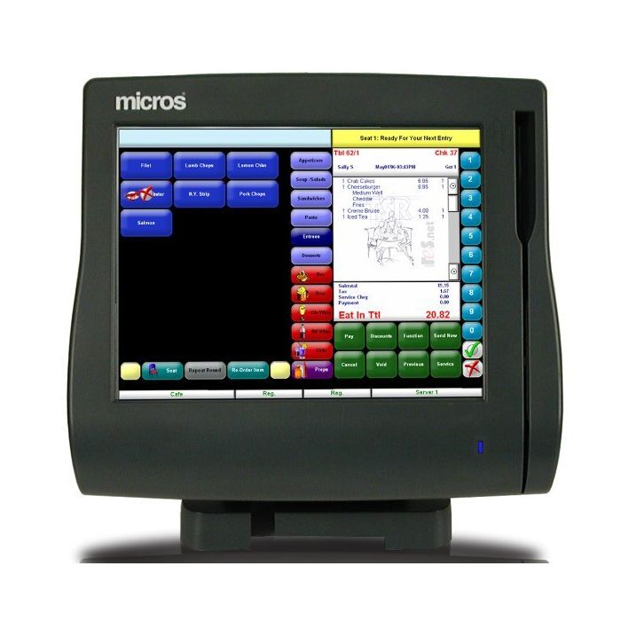
Micros WS4lx Workstation
|
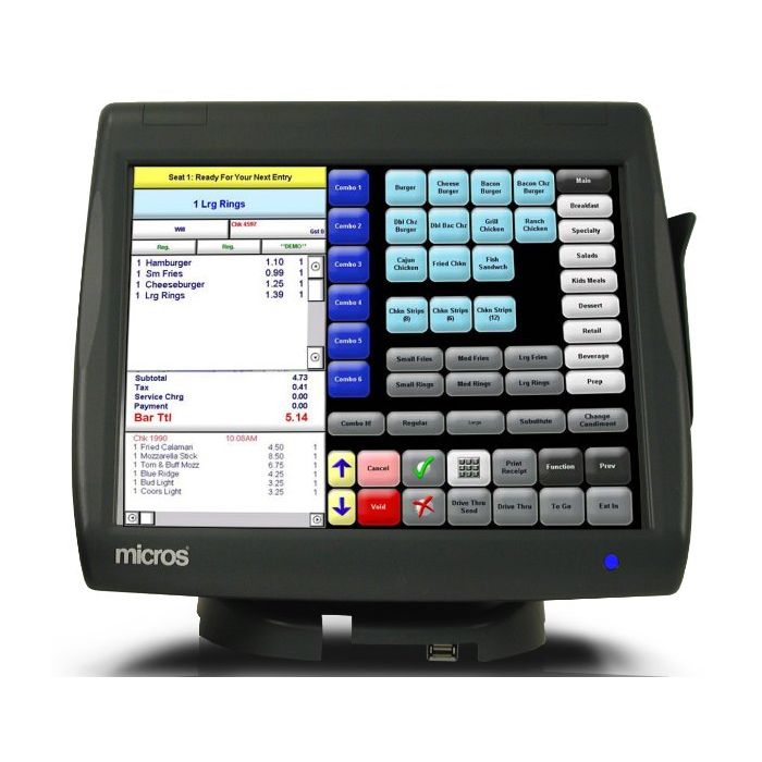
Micros WS5 Workstation
|
WS4 LX Troubleshooting
Workstation Recovery and Platform Update Procedures
Workstation Recovery and Platform Update Procedures
1. Connect a USB Keyboard to the workstation, and power-up.
2. Remove any USB thumb drives attached to the IO Panel USB connectors.
3. When the Blue BIOS splash screen appears, press the key combination [ALT-M].
Note: some keyboards may not initalize in time for the unit to detect this key
combination. As an alternative, you can press [Del] to enter BIOS Setup, select
the Features Configuration screen, and set the WIN_CE_FACTORY_RESTORE
field to 'Enabled.' Press [ESC] to continue.
•
The screen prompts for the system password.
4. If you have not changed the default system password, enter 'Hmlton' (case
sensitive) and press enter. Press 'Y' to confirm.
•
The screen returns to the Setup Main Menu.
5. Select 'Write to CMOS and Exit' and press enter. Press 'Y' to confirm.
•
The unit restarts and prompts 'Factory Restore in Progress - Please Wait.'
6. When the process is complete, the unit restarts. It should be connected to a
properly configured CAL or application server containing the latest platform
updates to ensure the unit is up to date.
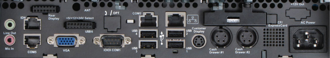
Micros WS5a Ports
Restolution
|
|
Upgrading SoftPos:
Open the terminal by pressing Alt + Shift + T
paste this:
wget http://repo.soft-contact.fi/nexus/repository/debs/softpos-20.06.1-r40734.deb
Press enter
It will fetch the package from the repsitory. After that is done, paste this:
sudo dpkg -i softpos-20.06.1-r40734.deb
Press enter
Restart Software
Alt + Shift + T
/etc/init.d/softpos restart
Restart Blackbox
Alt + Shift + T
sudo /etc/init.d/blackbox restart
Restart Cash Register
Alt + Shift + T
sudo reboot